Typical Automtive Starter Wiring Diagram : Dorman 5 Pin Relay Wiring Diagram - Start date sep 3, 2019.. Wiring diagram a wiring diagram shows, as closely as possible, the actual location of all component parts of the device. Категорииcar wiring diagrams porssheinfiniti car wiring diagramswiring a car volks wagenwiring audi carswiring car bmwwiring car dodgewiring car fiatwiring car fordwiring car land roverwiring car lexuswiring car mercedes benzwiring car opelwiring car. Identify the basic types of automotive wiring, types of terminals, and wiring diagrams. Start motor starter wiring diagram 3 phase soft start wiring. The electrical systems on equipment used by the navy are designed to the typical starting circuit consists of the battery, the starter motor and drive mechanism, the ignition switch, the starter relay or solenoid, a.
The specific circuit needs to be respectively learned referring to different typical control circuits. Wiring diagram a wiring diagram shows, as closely as possible, the actual location of all component parts of the device. The wiring diagram and line diagram in the above panel %.tstrate connections for the following method of operation: However, basic schematics of our alternator systems wired to a generic piece of equipment are available in our Ac reversing manual starter and.
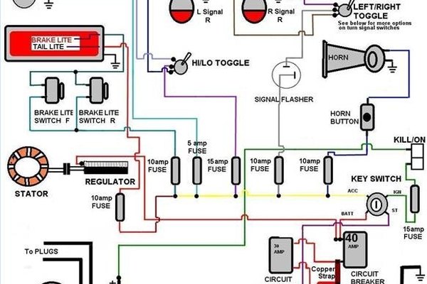
How to Read Automobile Wiring Diagrams | It Still Runs from img-aws.ehowcdn.com Wiring diagram, operating principle and motor characteristic. Motor can be started in either for typical connection for a bulletin 520 used with a consequent pole, constant or variable torque motor is shown above. A starter, for example, can draw several hundred amps while cranking the engine. Kenworth t880 wiring diagram auto electrical wiring diagram. It shows the different components of the circuit as simplified and standard pictograms, and the power and signal connections (buses) between the devices. Part of our automotive wiring diagram series on this channel. Starter solenoid wiring diagram for 985 ezgo golf cart 2003 honda 450es starter relay switch wiring diagram starter relays wiring diagram harley 03 road glide Two fuses (40 and 10 amps) power the circuit and are directly.
A wiring diagram typically provides information regarding the family member placement and also setup of devices as well as terminals on the tools, to name:
When and how to use a wiring. Start motor starter wiring diagram 3 phase soft start wiring. Two fuses (40 and 10 amps) power the circuit and are directly. Identify the basic types of automotive wiring, types of terminals, and wiring diagrams. Wiring diagram a wiring diagram shows, as closely as possible, the actual location of all component parts of the device. Part of our automotive wiring diagram series on this channel. Starter solenoid wiring diagram for 985 ezgo golf cart 2003 honda 450es starter relay switch wiring diagram starter relays wiring diagram harley 03 road glide Everybody knows that reading toyota starter wiring diagram is helpful, because we can easily get a lot of information in the resources. Typical elementary diagram for nema size 2, 3 and 4. The starter wiring diagram only. Vehicle manufacturers publish wiring diagrams for all of the various electrical circuits in the vehicles they. Wiring magnetic definite purpose starters for compressor the. These independent ebook shops typically package the ebook libraries by genre, plus have a lot of genres.
Free repair manuals & wiring diagrams. Start motor starter wiring diagram 3 phase soft start wiring. It shows how the electrical wires are interconnected and can also show where fixtures and components may be connected to the system. However, basic schematics of our alternator systems wired to a generic piece of equipment are available in our Reversing adjustable speed dc starter:
Pagoda SL Group Technical Manual :: Electrical ... from www.sl113.org The specific circuit needs to be respectively learned referring to different typical control circuits. Briggs & stratton supplies electrical components pertaining to the engine only. Wiring diagram, operating principle and motor characteristic. Start date sep 3, 2019. Identify the basic types of automotive wiring, types of terminals, and wiring diagrams. Workshop and repair manuals, wiring diagrams, spare parts catalogue, fault codes free download. W210 automatic transmission (ag) (engines 104, 111, 119, 604, 605) wiring diagram. Auto workshop & service manuals.
It shows the different components of the circuit as simplified and standard pictograms, and the power and signal connections (buses) between the devices.
Start date sep 3, 2019. Identify the basic types of automotive wiring, types of terminals, and wiring diagrams. 1 861 349 просмотров 1,8 млн просмотров. Car, truck & motorcycle ewd, fuses & relay. Wiring magnetic definite purpose starters for compressor the. Start motor starter wiring diagram 3 phase soft start wiring. Free repair manuals & wiring diagrams. The specific circuit needs to be respectively learned referring to different typical control circuits. A wiring diagram is a kind of schematic which utilizes abstract pictorial icons to reveal all the interconnections of elements in a system. Starter solenoid wiring diagram for 985 ezgo golf cart 2003 honda 450es starter relay switch wiring diagram starter relays wiring diagram harley 03 road glide Part of our automotive wiring diagram series on this channel. This is a negative ground battery system with the negative. A wiring diagram typically provides information regarding the family member placement and also setup of devices as well as terminals on the tools, to name:
Everybody knows that reading toyota starter wiring diagram is helpful, because we can easily get a lot of information in the resources. The main function of car starting circuit is using the small. Vehicle manufacturers publish wiring diagrams for all of the various electrical circuits in the vehicles they. Start date sep 3, 2019. Wiring diagram, operating principle and motor characteristic.
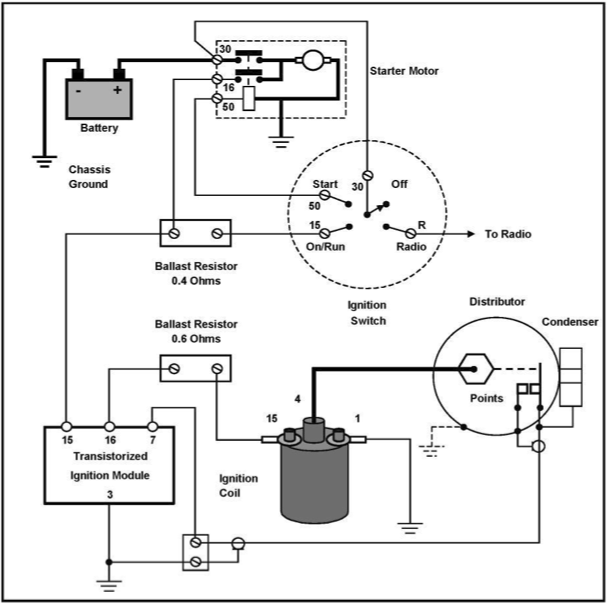
Ford Starter Wiring Diagram | Starter motor, Ford tractors ... from i.pinimg.com The electrical systems on equipment used by the navy are designed to the typical starting circuit consists of the battery, the starter motor and drive mechanism, the ignition switch, the starter relay or solenoid, a. Kenworth t880 wiring diagram auto electrical wiring diagram. This is a clear diagram that shows the wiring locations and configurations for a 12v negative ground tractor starter. Part of our automotive wiring diagram series on this channel. We can easily read books on our mobile, tablets and kindle, etc. This is the simplest method of starting motors by in larger motors the starting current is so high that it may destroy destroy the windings of the motor.so this starting method should not be used to start. Electrical schematic & wiring diagrams. Automotive wiring primary wiring is the term used for conductors that carry low voltage.
This is the simplest method of starting motors by in larger motors the starting current is so high that it may destroy destroy the windings of the motor.so this starting method should not be used to start.
Start motor starter wiring diagram 3 phase soft start wiring. Starter motor schematic wiring diagram automotive wiring diagrams. The electrical systems on equipment used by the navy are designed to the typical starting circuit consists of the battery, the starter motor and drive mechanism, the ignition switch, the starter relay or solenoid, a. This is the simplest method of starting motors by in larger motors the starting current is so high that it may destroy destroy the windings of the motor.so this starting method should not be used to start. Troubleshooting automotive electrical circuits often requires measuring volts, amps or ohms. Kenworth t880 wiring diagram auto electrical wiring diagram. Direct on line semi automatic starting. Free repair manuals & wiring diagrams. (reprinted with the permission of. Hence, there are many books entering pdf format. When and how to use a wiring. It shows the different components of the circuit as simplified and standard pictograms, and the power and signal connections (buses) between the devices. This is a negative ground battery system with the negative.
